



Production-Ready Jewelry CAD Checklist: 8 Structural Flaws to Catch Before Tooling
In modern jewelry product development, a common and costly misconception among independent designers and brand managers is assuming that: "If my 3D CAD model renders beautifully and 3D prints successfully in resin, it is ready for mass production."
In actual factory production, 3D printing a polymer model ≠ investment casting molten precious metal ≠ repeat mass manufacturing.
Resin does not undergo thermal contraction, does not require molten metal fluid velocity, and does not need to be physically reached by a high-speed rotating polishing wheel. When a digital file is moved into silicone tooling and lost-wax casting without Design for Manufacturability (DFM) verification, brands inevitably face warped bands, collapsed hollow walls, snapped stone prongs, and massive tooling rework fees.
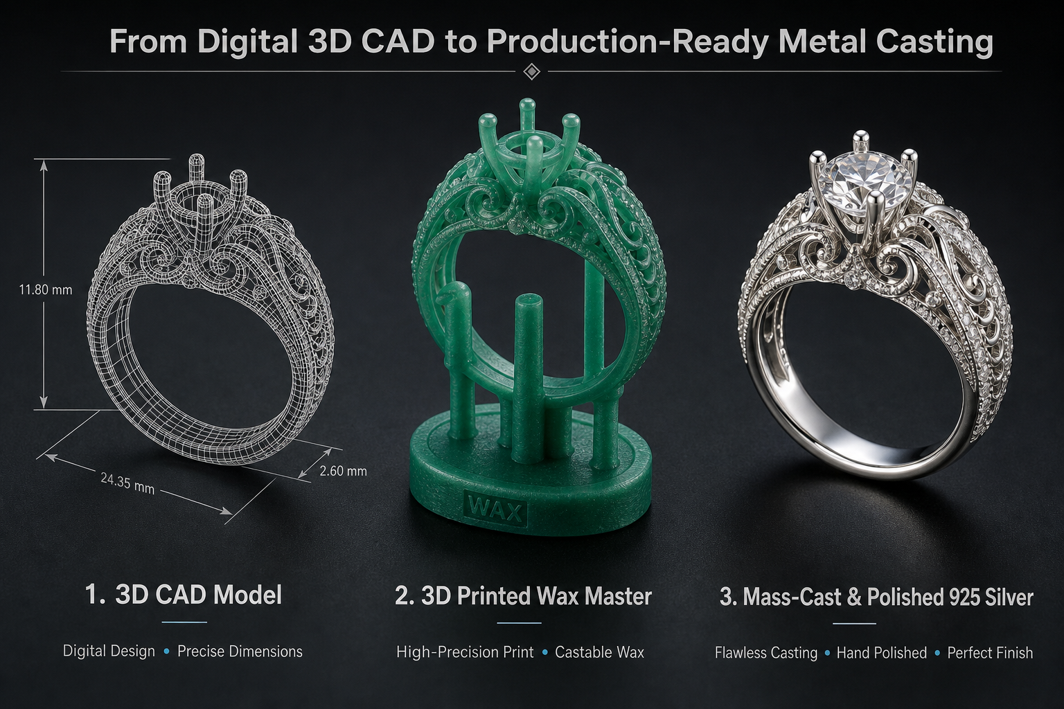
Figure 1: The 3-stage validation progression: Digital 3D Mesh → 3D Printed Castable Wax → Engineered 925 Silver Production Piece.
1. The 3D Print vs. Lost-Wax Casting Paradox
When an SLA or DLP 3D printer cures liquid photopolymer resin layer by layer, it can produce razor-thin edges (0.2mm) and complex enclosed lattices that look stunning on a display tray. However, investment casting introduces aggressive physical forces:
- Liquid Metal Surface Tension & Thermal Chill: Molten 925 silver or brass freezes rapidly upon entering cold plaster cavities. Walls under 0.75mm frequently suffer incomplete filling (short shots) or porous grain boundaries;
- Solidification Contraction: Precious metals contract by approximately 2.0% to 2.5% as they transition from liquid to solid, distorting uncompensated ring sizes and stone seat diameters;
- Post-Casting Finishing Loss: As detailed in our guide on Why Manufacturing Charges Differ (Manual 执磨 & Polishing), every cast piece must be filed and buffed, stripping another 0.05mm–0.10mm of surface metal.
2. The 8 Critical CAD Flaws to Audit Before Tooling
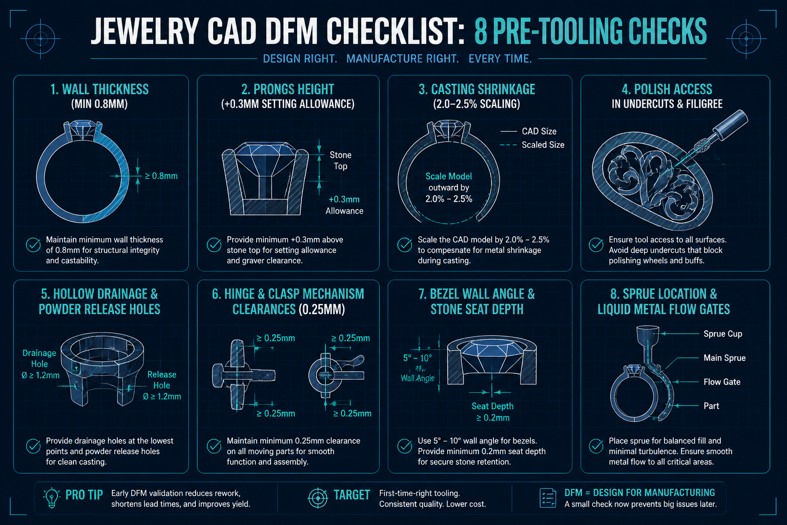
Figure 2: AIU Jewelry‘s 8-point engineering checklist for pre-tooling CAD verification.
Before freezing your 3D CAD files for master rubber mold injection, review every design against these 8 industrial engineering thresholds:
| CAD Flaw / Checkpoint | Factory Failure Mechanism | AIU Engineering Standard |
|---|---|---|
| 1. Wall Thickness Under 0.8mm | Incomplete casting filling, fragile deformation, burn-through during polishing. | Minimum 0.80mm–0.90mm for 925 silver bands; minimum 0.70mm for earring hollows. |
| 2. Flush Prong Height | Setter has no metal to fold over gemstone; stones loosen or fall out during wear. | Prongs modeled +0.25mm to +0.35mm higher than stone girdle + 0.15mm thickness safety allowance. |
| 3. Uncompensated Shrinkage | Rings end up half a US size too small; bezel cups cannot seat custom-cut stones. | Scale CAD file up uniformly by +2.0% to +2.5% prior to 3D printing wax masters. |
| 4. Trapped Undercut Dead Zones | Felt wheels and abrasive brushes cannot physically reach recesses, leaving black casting scales. | Provide minimum 1.2mm tool clearance or engineer multi-component split assemblies. |
| 5. Enclosed Hollows without Drainage | Investment plaster cannot be washed out, trapping toxic chemicals; exploding during soldering. | Incorporate dual drainage escape holes (≥ 1.0mm diameter) at hidden concave points. |
| 6. Zero-Tolerance Hinge Joints | Molten metal fuses moving parts together; electroplating locks the mechanism shut. | Maintain 0.25mm–0.30mm mechanical gap between moving knuckles and rivet pins. |
| 7. Knife-Edge Bezel Walls | Bezel splits when hammered; sharp edges tear customer clothing. | Bezel top thickness minimum 0.45mm with 12° inward draft angle for smooth burnishing. |
| 8. Sprue Gate Placement Over Details | Cutting the casting sprue destroys laser engraving, hallmarks, or delicate gemstone prongs. | Designate smooth, heavy cross-sectional areas (bottom of ring shank) for sprue entry points. |
3. The Mechanics of Shrinkage: Why Stone Seats Fail
One of the most frequent friction points between jewelry brands and overseas OEM factories is gemstone fit. If you design a bezel or collet for a 6.00mm round brilliant Moissanite or natural Moss Agate:
- The raw casting shrinkage will reduce that seat to 5.86mm;
- If the CAD modeler modeled the seat at exact 6.00mm, the setter will be forced to grind out the precious metal with a ball bur, weakening the seat wall and adding costly labor hours.
In our factory‘s DFM process, every stone seat CAD layer is parameterized against the specific stone tolerance (+0.10mm for natural gemstones, +0.05mm for calibrated lab stones) and pre-scaled for master casting shrinkage.
4. Polishing Wheel Accessibility & Split-Part Engineering
A jewelry piece is only as luxurious as its least polished surface. In Gothic, floral, or multi-layered architectural jewelry, designs often feature deep valleys under 1.0mm wide.
Instead of struggling to cast an intricate ring as a single monolithic block that cannot be polished inside, our engineering team breaks the CAD model into 2 or 3 interlocking sub-components (Split Assembly). Each piece is cast, machine-buffed, hand-polished to mirror perfection on all interior faces, and then precision laser-welded together.
5. AIU‘s 24-Hour DFM Pre-Tooling Audit Protocol
To eliminate sampling surprises and protect brand margins (especially in high silver price environments, see our analysis on Silver Weight Variance Control), AIU Jewelry provides a mandatory 4-step DFM audit before any master mold is cut:
- Cross-Section Thickness Heatmap: Full STL/3DM inspection to highlight any wall sections below 0.8mm;
- Fluid Dynamics & Sprue Positioning: Simulating molten metal flow paths to position sprues away from delicate aesthetics;
- Stone Setting & Clasp Clearance Review: Cross-checking prong heights against your physical stone parcel dimensions;
- Weight & Plating Feasibility Simulation: Calculating theoretical cast weight and confirming suitability for heavy Gold Vermeil plating (see Plating Thickness Guide).
Frequently Asked Questions (FAQ)
Q1: What 3D CAD formats does AIU Jewelry accept for tooling review?
We natively support native Rhino (.3dm), MatrixGold, JewelCAD, STEP (.stp), and high-density watertight mesh files (.stl). For initial feasibility quotes, 2D vector Tech Packs (PDF/AI) are also welcome (download our Jewelry Tech Pack Checklist).
Q2: If our CAD model was created for 3D resin printing, can AIU modify it for casting?
Yes. Our in-house CAD engineering department routinely optimizes designer 3DM/STL files—adjusting wall thicknesses, adding stone setting allowances, and pre-scaling shrinkage ratios before opening master tooling.
Q3: How does proper CAD engineering reduce my final unit cost?
Correct DFM modeling prevents porosity scrap, eliminates manual bench filing corrections (执磨), and optimizes internal hollowing—reducing precious metal weight while maintaining rigid structural integrity.
Ready to Transform Your CAD Concepts into Flawless Production?
Send us your 3D CAD files or sketch concepts today. Our engineering team will return a comprehensive DFM manufacturability review and transparent tooling quotation within 24 hours.
Submit CAD Files for Free DFM Review anya907888